|
|
Cheshire Rail
Turnout Control
The Cheshire Rail track plan includes eleven turnouts. Early in the design process, I determined I wanted Code 55 track. Atlas was not the only choice of Code 55 track, but it seemed like the best choice for my needs. As a result, the layout includes four #5 lefthand turnouts, three #7 lefthand turnouts, three #7 righthand turnouts, and just for a little variety, one #3.5 wye. I briefly considered using Atlas curved turnouts in a couple of spots, but they were difficult to obtain at the time, so I went ahead without them.
Moving the Points: A Manual Method
Now came the important decision of how to move the points of the turnouts. I considered many options! I installed manual controls for the first few turnouts, using small DPDT (double-pole, double-throw) slide switches that both moved the points and provided contacts for switching frog polarity and powering LEDs for my control panel.
DPDT slide switches for turnout control. (Click images for larger version.)
Although the slide switches worked pretty well, this solution was too "low tech" for my taste. I had come to realize that electronics and even computerization were aspects of the model railroad hobby that interest me. My layout would be DCC anyway, so why settle for manual turnout control, when half the fun (for me!) would be doing it with electronics?
Moving the Points: Remote Control
When I was constructing my layout there were several products for remotely moving turnout points, including the popular Tortoise Slow Motion Switch Machines. I considered Tortoises, but they were expensive and bulky. Stepper motors might have worked. I even had a few on hand and had previously built a stepper motor controller for an astronomy project. But steppers seemed unnecessarily complicated for controlling N-scale turnouts. Then I heard about model railroaders using servos of the type utilized in radio controlled (R/C) aircraft.
Servos appealed to me for several reasons:
- I was already building and flying small R/C aircraft, so I had some spare micro servos on hand.
- Electronic circuits for controlling servos were very simple, and I had all of the components needed to build them.
- Micro servos are really small and would fit easily in spaces too small for other turnout motors such as Tortoises or stepper motors.
I scoured the web for servo control circuits and found several that would do the job (I thought). But the more I considered the matter, the longer my list of requirements became. I wanted a solution that would:
- Move the points with pushbuttons on a control panel.
- Move the points using a DCC controller.
- No matter which method of moving the points was used, illuminate LEDs on a control panel to indicate the current position of the points.
- Switch polarity of the turnout frog when the points are moved.
- Allow easy adjustment of servo speed and endpoints.
- Allow eventual integration with JMRI (Java Model Railroad Interface).
- Be less expensive than Tortoises.
I soon realized that the design and construction of homemade turnout controllers that could handle ALL of these requirements would entail a steep learning curve and consume a lot of time. (This was before Arduino and Raspberry Pi single-board computers were readily available.) So I turned to ready-made products from Tam Valley Depot. The following Tam Valley items were needed for the eleven turnouts on my layout:
- 3 Quad-Pic Servo DCC Decoders.
- 3 Quad SPDT relay boards (for frog polarity switching).
- 11 LED Fascia Controllers with pushbutton.
Note: The product lineup at Tam Valley Depot has changed since I bought the items for my layout, but the functionality I wanted is still available. The original items I purchased are still performing just fine after more than a decade. I have no affiliation with Tam Valley Depot other than being an early and very satisfied customer.
Click to read my Tam Valley Servo Decoder Mini-Review.
One of the most convenient aspects of using servos for turnout control is that all of the components (servos, circuit boards, and fascia controllers) interconnect with servo cables that are readily available nearly everywhere R/C products are sold. No soldering is required except for one wire that must be connected to the frog of each turnout to control its polarity!
Moving the Points: Turnout Control Linkage
After deciding to use servos for throwing turnouts, the next question became: What sort of linkage should I use between the servos and the points?
I gave some consideration to the wire-and-fulcrum type of linkage typically used with Tortoises. While this would work pretty well for most of the turnouts, there were some locations on the layout where the turnout linkage needed to operate through several inches of benchwork, subroadbed, and scenery. The Tortoise type of linkage is awkward in such situations, so I adopted a different type of linkage — known as a bellcrank — that works well through any layout thickness. I have used this type of linkage through as much as 6 inches of benchwork, subroadbed, and scenery.
Note: Bellcrank linkages are widely used in R/C aircraft to connect servos to controls surfaces (rudders, ailerons, and elevators). However, I had never seen them used for turnout control in model railroading. I subsequently discovered that other railroaders were already using the bellcrank method, so I was merely re-inventing a system that others had implemented before it ever occurred to me. Therefore, I make absolutely no claim of originality for this method!
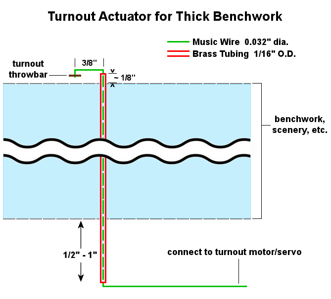
When installing one of these turnout actuators, I make only one measurement: the 3/8-inch distance from the turnout throwbar to the hole where the 1/16-inch brass tubing is located. Everything else is easily done by eye. No jigs or templates are needed. The actuators are installed after the turnouts are in place on your layout. With practice, you can install one in 10-15 minutes.
Note: My railroad is N-scale. If yours is a larger scale, such as HO, you'll want to place the brass tubing more than 3/8-inch from the turnout throwbar. A distance of 3/4-inch should work well for HO.
Materials required are 1/16-inch brass tubing and 0.032-inch music wire (also known as piano wire or spring steel wire). The tubing and wire are available from any well-stocked hobby store that serves R/C aircraft enthusiasts. You can also purchase the items from many online stores, including Amazon. The leading maker of these materials for the hobby market is K&S Precision Metals.
Here's the basic idea for the turnout actuator:
Installation steps are as follows.
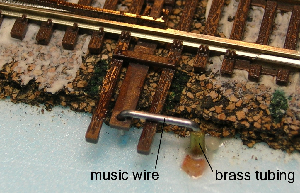
- Select a location for the brass tubing, as shown in the photo below. I use a location that is 3/8-inch (0.375 inch) from the hole in the turnout throwbar. See the diagram above. This is the only step where I measure anything, but even here extreme precision is not necessary. A little more or less than 3/8-inch is fine.
Turnout linkage, top of layout. (Click image for larger version.)
- Drill a hole through your layout for the brass tubing. If you are installing through several inches of benckwork and scenery, you'll need an extra long 1/16-inch (0.0625 inch) drill bit. I found mine at a large home center (Lowes). But you can also purchase 6-inch and even 12-inch drill bits online. Use Google and search for "aircraft" or "long boy" drill bits.
- After drilling, insert a piece of 1/16-inch brass tubing into the hole from the top of the layout. At this point, simply make sure it is about an inch longer than the thickness of your benchwork and scenery. Push in the tubing until about 1/2-inch of it protrudes from the underside of the layout. On the top of the layout, mark the tubing where it emerges above the layout. Now pull the marked tubing out of the layout and use a razor saw to cut it to length approximately 1/8-inch above your mark. De-burr the openings at either end of the tubing so the music wire can slide in freely. I used a dull #11 Xacto blade for de-burring.
- Re-insert the cut piece of brass tubing into the layout until only about 1/8-inch extends above the top of the layout. Friction may be enough to hold the tubing in place, but I use a dot of glue to be sure.
- Cut a piece of 0.032-inch music wire that is at least a couple of inches longer than the brass tubing. You'll trim it later. Music wire is cheap, so be generous. Important Tip: Do not attempt to cut music wire with the small wire cutter you use for cutting hookup wire; you will ruin your wire cutter. At a minimum, use the cutter built into large needlenose pliers, or better yet, use a heavy diagonal cutter or lineman's pliers. The spring steel music wire is tough stuff!
- Make a 90° bend approximately 3/4" (no need for precision here) from one end and drop the music wire into the tubing from the top of the layout (the bend keeps it from falling through).
- With the wire inserted in the tubing, lay the bent portion of the music wire across the throwbar and note the location of the hole in the throwbar. Use two needlenose pliers to grip the wire and make a small downward bend so that the end of the wire can drop into the hole in the throwbar. If the downward bend is too long, trim off the excess. This is all done by eye without measuring anything.
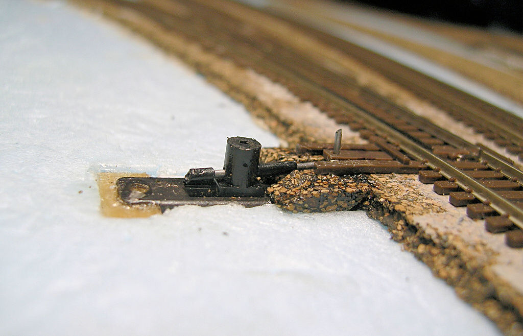
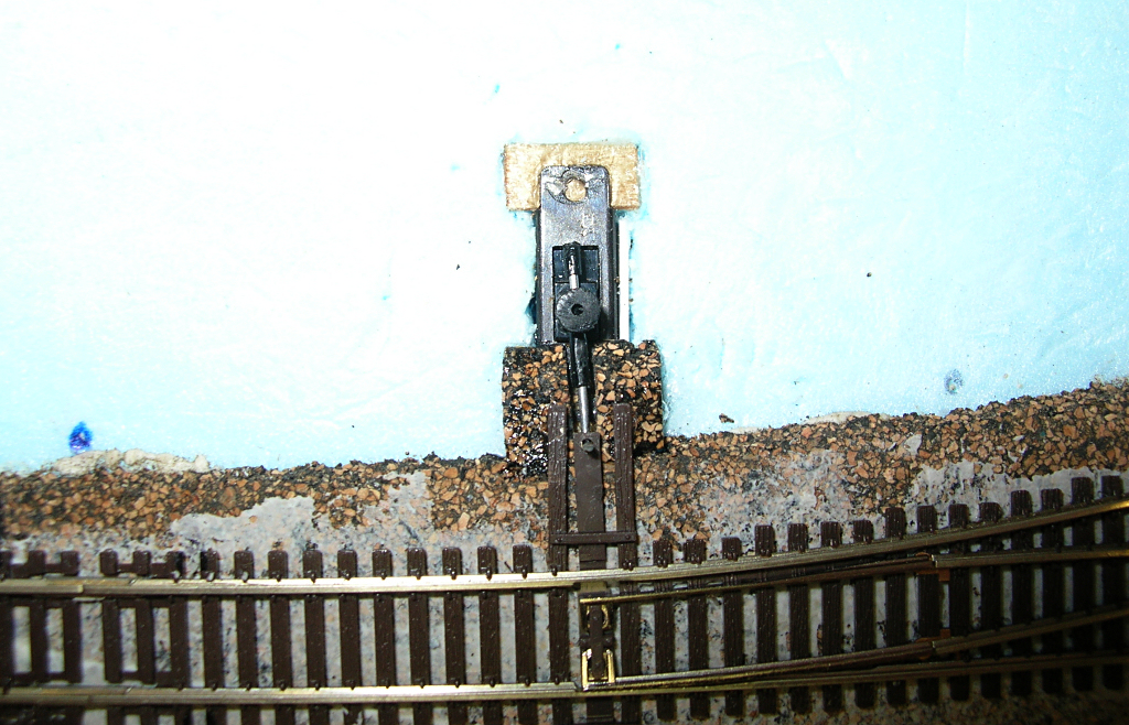
- On the underside of the layout, you'll have an inch or more of music wire protruding out of the tubing. After you determine a convenient location and orientation for the servo, make a 90° bend in the music wire where the wire exits the bottom of the tubing. Bend it toward the location where you intend to mount the servo. You can bend the music wire in any convenient direction, so you have considerable freedom on where you mount the servo. Trim the length of the music wire if it's too long.
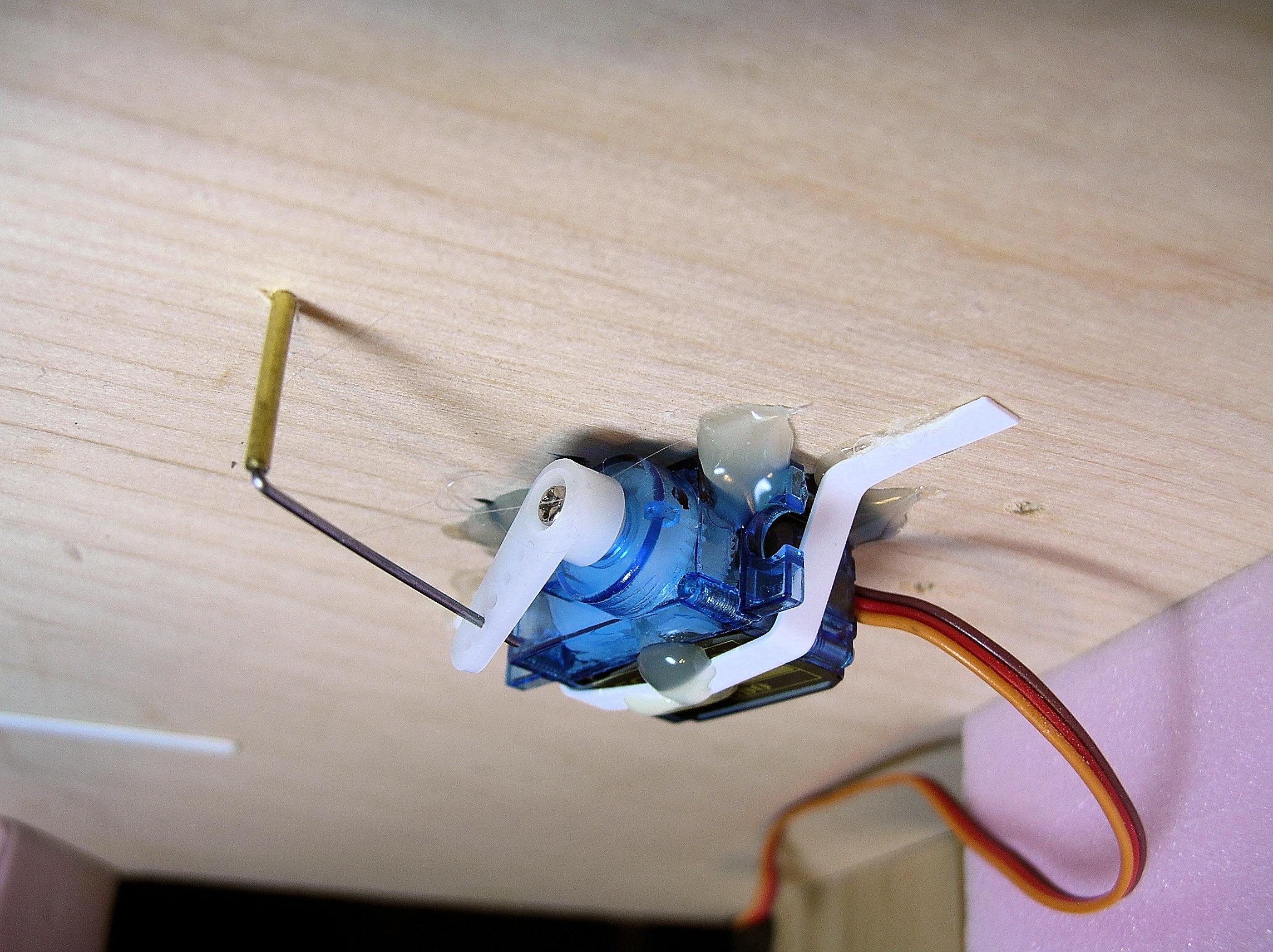
Turnout linkage, bottom of layout. (Click image for larger version.)
- Mount the servo securely to the underside of the layout. I used hot glue and a strap made of styrene as shown above. Insert the music wire into one of the holes in the servo arm, then attach the arm to the servo. I use the second hole from the end of the servo arm. In use, as the servo arm moves from side to side, the music wire will rotate inside the brass tubing, causing the turnout's throwbar to move the points.
- Plug the servo into the control board of your choice and adjust the servo throw according to the instructions for your servo control board. I use control boards from Tam Valley Depot, but there are other manufacturers whose boards will work just as well.
|